RPZ Valve
Chemical attack inside a valve rarely announces itself. A pale stain, a roughened seat, or a pinhole beneath a coating may be the first warning. The damage is gradual. Yet an incorrect alloy, aggressive fluid, or fast-moving slurry can turn small defects into leakage and unplanned shutdowns.
NACE International’s 2016 IMPACT study estimated global corrosion costs at US$2.5 trillion annually, or 3.4% of global GDP. This estimate covers many industries, not valve failures alone, so it should not be treated as a valve-specific forecast. Corrosion scientist Herbert H. Uhlig described the mechanism as “the destructive attack of a metal by chemical or electrochemical reaction with its environment.” That definition helps explain why fluid chemistry, temperature, pressure, and material selection matter together.
This guide explores how to prevent chemical erosion on valve components through practical checks: matching materials to process media, managing flow velocity, inspecting vulnerable surfaces, and planning maintenance around operating conditions. A valve handling acidic condensate needs different safeguards from one carrying abrasive slurry. There is no universal coating or alloy. Even careful specifications can miss changing chemistry or unexpected contaminants; that limitation deserves attention, not a footnote. The seven tips that follow offer a starting point for better decisions, but site data and qualified engineering review remain essential.
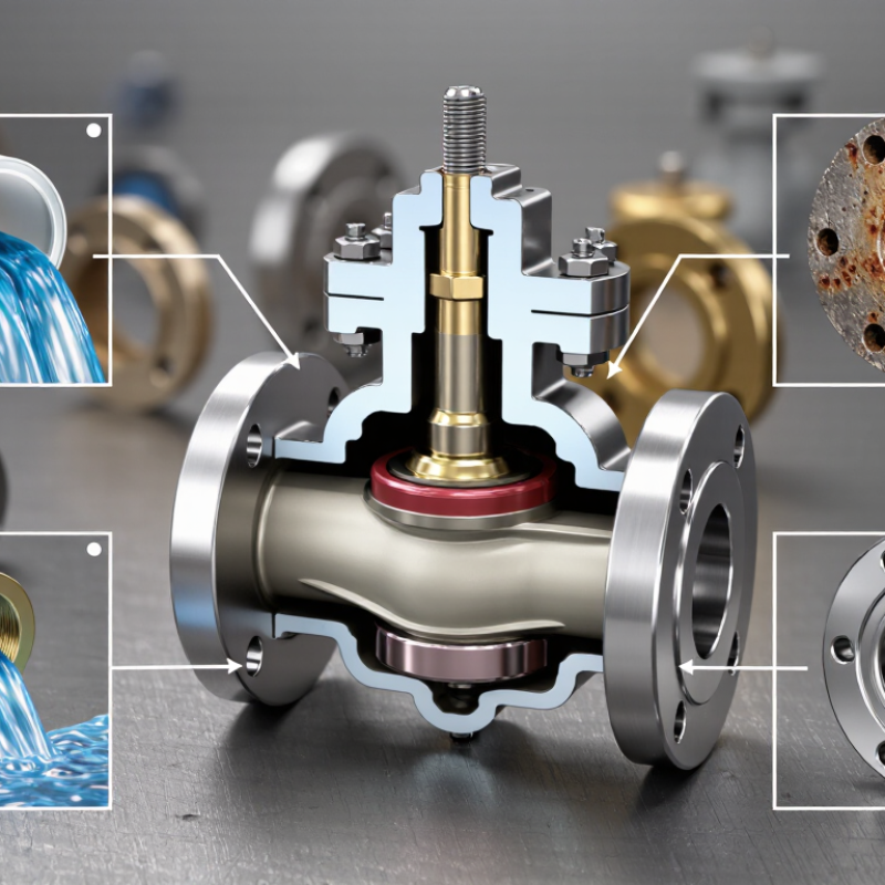
Chemical attack often starts where fluid chemistry changes or deposits trap moisture. Record pH, chloride concentration, temperature, dissolved oxygen, and operating cycles. Small shifts matter. A sample taken during steady operation may miss a harsh cleaning cycle or startup condition. That gap is worth noting.
Use ASTM G31 to plan controlled immersion tests and estimate corrosion rates from mass loss. Document specimen dimensions, surface finish, exposure time, solution volume, and cleaning procedure. Include material samples from valve bodies, trim, and weld regions when practical. Compare results across alloys under the same conditions. Keep records; inconsistent preparation can distort the rate.
ASTM G48 helps assess pitting and crevice corrosion resistance in stainless steels and related alloys using ferric chloride solutions. Select the applicable test method and report temperature, duration, and observed attack. Inspect edges, gasket-contact areas, and narrow gaps, not just broad surfaces. G48 is deliberately severe, so it does not predict field life by itself. Pair its findings with G31 data and actual service chemistry. Lab work can still miss an unusual deposit or intermittent contaminant. That uncertainty should stay visible in the valve material decision.
For H₂S-bearing production fluids, select valve materials against the actual service environment—not a generic “sour-service” label. ISO 15156 (NACE MR0175) provides requirements for materials resistant to cracking in H₂S-containing oil and gas environments. Assess H₂S partial pressure, pH, temperature, chloride concentration, and the presence of elemental sulfur. These factors can change whether a material is suitable. A grade name alone is not enough.
The standard’s material-selection guidance and qualification limits should be checked for the specific product form, hardness, heat treatment, and operating conditions. Keep mill certificates and test records traceable to each pressure-containing component.
A 2016 NACE IMPACT study estimated corrosion costs at US$2.5 trillion globally, or 3.4% of GDP, and potential savings from corrosion-control practices at 15–35%. Those figures cover corrosion broadly, but they show why early material review matters. Not a checkbox.
Tip
Record the worst credible H₂S pressure, temperature, and water chemistry. Confirm the selected material meets ISO 15156 limits for those conditions, then review deviations with a qualified materials specialist. A spreadsheet helps, but it cannot replace verified operating data. Recheck assumptions when fluid composition or process conditions change; that step is easy to overlook.
316L stainless steel typically contains 2–3% molybdenum, which improves resistance to chloride-induced pitting compared with 304 stainless steel. In a valve, that difference matters around wetted surfaces, stems, and small cavities where salty water can linger. Molybdenum helps. It does not make the alloy immune to corrosion.
Temperature, chloride concentration, surface condition, and stagnant flow all affect performance. Warm brine trapped beneath a gasket can attack a component even when the bulk fluid seems mild. Keep valve cavities clean, avoid unnecessary dead legs, and flush deposits during maintenance. A smooth, properly finished surface is easier to clean, though it cannot prevent every localized attack. Weld quality and post-weld cleaning also deserve attention; 316L’s low carbon content reduces sensitization risk, not chloride pitting itself.
Check the actual alloy certificate rather than relying on a material label alone. Then compare the service conditions with corrosion data or a representative test. That step can feel excessive for a small valve. It is still useful when failure would cause downtime. Inspect for tiny pits near seals and threaded joints, where early damage may be easy to miss. If chloride levels or temperatures vary, reassess the material choice instead of assuming 316L will always be adequate.
API RP 14E estimates erosional velocity with Ve = C/√ρm, where Ve is in feet per second and ρm is mixture density in pounds per cubic foot. The practice lists C values of 100 for continuous service and 125 for intermittent service. Treat these as screening values, not safe operating limits. A useful screen. Recalculate using actual operating conditions, because pressure, temperature, gas fraction, and liquid density affect the result.
Compare calculated velocity with measured or modelled flow through each component. Check elbows, reducers, tees, and valve outlets; turbulence and impingement can concentrate wear in small areas. API RP 571 describes erosion-corrosion as a damage mechanism associated with high velocity and turbulent flow. Solid particles or liquid droplets can accelerate damage, even when a bulk-flow calculation looks acceptable. Not a guarantee. Inspect for localized thinning, and track wall thickness at repeatable measurement points. If the formula suggests a comfortable margin, resist the temptation to raise the C value without evidence. That shortcut is easy, and may be wrong. Use inspection history and fluid analysis to refine the operating limit.
| No. | Prevention tip | Component / damage driver | Practical control | Useful check |
|---|---|---|---|---|
| 1 | Confirm chemical compatibility | Body, bonnet, stem, seat, and trim exposed to process fluids | Select materials using the actual fluid composition, concentration, temperature, pressure, and contaminants. Consider localized corrosion as well as general corrosion. | Review process chemistry and material compatibility before specifying or changing service conditions. |
| 2 | Screen flow velocity | High-velocity flow can contribute to erosion, especially when droplets or solids are present. | Use Ve = C / √ρm as an initial piping screen, then assess valve geometry, operating range, and multiphase-flow conditions separately. | Illustration at C = 100: ρm = 50 lb/ft³ gives Ve ≈ 14.1 ft/s; 62.4 gives ≈ 12.7 ft/s; 80 gives ≈ 11.2 ft/s. |
| 3 | Limit solids and entrained droplets | Particles and liquid droplets can accelerate wear on seats, plugs, cages, and downstream surfaces. | Use suitable upstream separation or filtration where the process allows; investigate abnormal sand, scale, or liquid carryover rather than relying on velocity alone. | Trend solids loading, filter differential pressure, separator performance, and trim wear found during inspection. |
| 4 | Reduce direct impingement | A concentrated jet or particle-laden flow can strike trim and body surfaces repeatedly. | Review flow direction and valve internals for the duty. Where appropriate, use replaceable trim and erosion-resistant materials selected for the fluid’s chemistry and temperature. | Check recurring wear location, flow direction, and whether damage is concentrated opposite a port or at a trim outlet. |
| 5 | Assess cavitation and flashing | Pressure reduction across a valve may cause vapor formation and collapse or persistent vapor flow, damaging trim and nearby surfaces. | Size the valve for the full operating envelope and evaluate pressure-drop management or staged pressure reduction where the service warrants it. | Compare inlet and outlet pressure, temperature, fluid vapor pressure, noise, vibration, and observed trim damage. |
| 6 | Track condition over time | Unnoticed wall loss, leakage, or progressive trim damage can increase failure risk. | Set inspection intervals based on service risk and operating history. Use inspection methods appropriate to the component and access; compare findings with a recorded baseline. | Trend wall-thickness readings where suitable, leakage, actuator demand, and documented trim condition. |
| 7 | Manage process chemistry | Changes in pH, water content, dissolved gases, or chemical treatment can alter corrosion behavior. | Maintain controlled operating chemistry and verify that inhibitors or treatment chemicals are suitable for the materials and process. Do not treat chemical corrosion as flow erosion. | Review chemistry trends and correlate them with inspection findings, leaks, and material damage. |
Note: The API RP 14E relationship is empirical and is not a valve-specific guarantee against erosion. Confirm the applicable edition, design basis, fluid properties, and service-specific requirements with a qualified engineering assessment.
Valve trim can appear intact while chemical attack quietly thins an edge or lifts a coating. Validate materials against the actual process fluid, including concentration, temperature, contaminants, and cleaning chemicals. A test using only the main fluid may miss the condition that causes failure. Small details matter.
Expose trim samples and coated coupons to representative service conditions before specifying them. Track mass loss, dimensional change, pitting, and coating adhesion. Check coating thickness and look for pores or bare spots, especially around sharp edges and drilled passages. A clean-looking surface is not proof of protection.
During inspections, compare the same locations over time and record photographs, operating conditions, and any measured damage. Use consistent methods, such as visual examination and suitable nondestructive checks, so changes are easier to identify. Testing is imperfect. Laboratory exposure cannot fully reproduce every flow pattern or temperature cycle in service, so field findings should inform the next review. If a coating blisters or trim shows unexpected attack, pause and reassess the material choice rather than assuming the damage is isolated.
Record pH, chloride concentration, temperature, dissolved oxygen, and operating cycles. Include cleaning and startup conditions. Small shifts matter.
It supports controlled immersion tests and corrosion-rate estimates from specimen mass loss. Record sample dimensions, surface finish, exposure time, solution volume, and cleaning procedure. Preparation differences can skew results.
It assesses pitting and crevice-corrosion resistance using ferric chloride solutions. Inspect edges, gasket-contact areas, and narrow gaps. Not field life. Pair results with service-fluid data.
Consider H₂S partial pressure, pH, temperature, chloride concentration, and elemental sulfur. Check the material’s product form, hardness, heat treatment, and operating limits. A grade name alone is insufficient.
Trace records to each pressure-containing component. This helps verify material suitability and investigate later problems. A spreadsheet can help, but it cannot fix unverified operating data.
Treat it as a screening estimate, not a safe operating limit. Recalculate with actual mixture density and operating conditions. A screen only.
Check elbows, reducers, tees, and valve outlets, where turbulence or impingement can concentrate wear. Track wall thickness at repeatable points. Small areas can hide damage.
Recheck them when fluid composition or process conditions change. Compare calculations with inspection history and fluid analysis. This step is easy to miss.
Preventing chemical erosion on valve components begins with understanding the fluid and operating conditions. Characterize the fluid’s chemistry and use suitable corrosion tests, such as ASTM G31 and ASTM G48 methods, to compare material performance and estimate corrosion risks. For equipment exposed to hydrogen sulfide, select materials in accordance with ISO 15156 requirements. In chloride-containing environments, assess whether 316L stainless steel, with its molybdenum content, offers adequate resistance for the specific application.
Flow conditions also matter: excessive velocity and entrained particles can accelerate wear, so apply the API RP 14E erosional-velocity formula as a screening tool alongside sound engineering judgment. Finally, validate valve trim and protective coatings through testing under representative service conditions, then use regular inspection to detect damage early. Together, these steps offer a practical approach to how to prevent chemical erosion on valve components and improve valve reliability over time.
