 RPZ Valve
RPZ Valve
RPZ Valve
A precision valve ball may look flawless under workshop lighting, yet a tiny deviation can create uneven contact, leakage, or accelerated seat wear. That is why engineers must understand how to measure the roundness of a precision valve ball before accepting its quality. Roundness is not the same as diameter. A ball can meet its diameter tolerance while still showing form error across different rotational positions.
Industry market analyses from Grand View Research and MarketsandMarkets identify reliability, sealing performance, and process consistency as major priorities in industrial valve purchasing. These priorities make ball inspection more than a final paperwork exercise. It becomes a control point for safety and operating life. ISO 1101:2017 defines geometrical tolerancing principles, while ASME B89.3.1 provides recognized guidance for roundness measurement. ISO 5208 also connects valve performance with pressure testing and leakage evaluation.
In practice, technicians may use a high-accuracy roundness tester, a calibrated rotary table, or a coordinate measuring machine. The ball is cleaned, supported carefully, and measured through several meridians. Probe pressure must remain controlled. Even a fingerprint can influence delicate results.
Small details matter.
The result is usually reported as the radial distance between the highest and lowest measured points. However, the measurement method, filtering settings, datum selection, and environmental temperature can change the outcome. This is where many explanations become too confident. A perfect result on one instrument does not guarantee perfect performance in service. Engineers should compare the roundness profile with the seat design, material condition, inspection uncertainty, and applicable customer specification. Reliable measurement requires both sound equipment and thoughtful judgment.
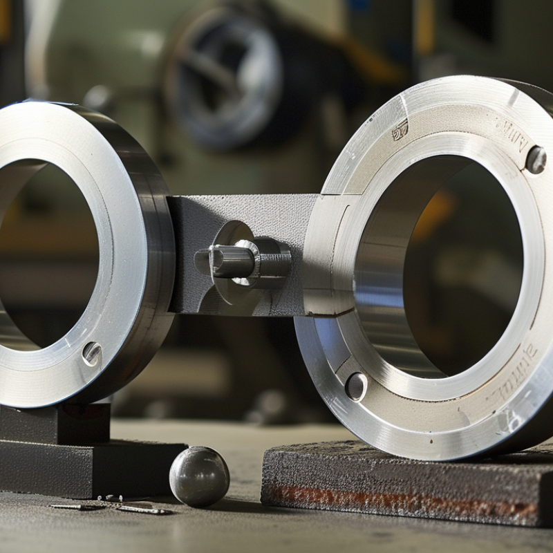
Defining roundness requirements is the real starting point for a precision valve ball. A measurement has little value without an agreed acceptance limit. Specify roundness as the maximum radial separation between two concentric circles. State the tolerance in micrometres, such as 2 μm, and define the ball diameter separately. Diameter controls fit. Roundness controls uniform contact.
Connect the requirement to valve performance. A sealing ball may need a tighter tolerance than a ball used only for positioning. Consider pressure, temperature, sealing material, rotation speed, and expected service life. Record the measurement temperature, usually near 20°C, because thermal expansion can change results. Define the inspected surface, sampling locations, filtering method, and instrument accuracy. A calibrated roundness tester or coordinate measuring machine can examine several great-circle paths, not just one convenient section.
In production work, repeatability matters. Use the same fixture and contact force for every inspection. Avoid clamping marks. They can distort the reading. A tolerance below the instrument’s reliable resolution is not a serious requirement. This is often overlooked. A tight specification may sound professional but remain impossible to verify. Review actual leakage data, machining capability, and inspection variation before final approval. Leave room to challenge the first draft. Real operating evidence may show that the initial limit is either excessive or insufficient.
| Nominal Ball Diameter | Typical Valve Application | Recommended Roundness Requirement | Recommended Diameter Tolerance | Preferred Measurement Method | Minimum Measurement Resolution | Sampling Guidance | Acceptance Basis |
|---|---|---|---|---|---|---|---|
| 6–12 mm | Miniature metering or instrumentation valve | ≤ 0.5 µm | ±1.0 µm | High-accuracy roundness tester or calibrated scanning CMM | ≤ 0.05 µm | At least 8 angular traces at two or more axial positions | Maximum radial deviation |
| 12–25 mm | High-pressure instrumentation or laboratory valve | ≤ 0.8 µm | ±1.5 µm | Roundness tester with rotary spindle error compensation | ≤ 0.1 µm | Measure multiple meridians and rotate the ball at least 90° between setups | Least-squares or minimum-zone result, specified in advance |
| 25–50 mm | Precision process-control ball valve | ≤ 1.5 µm | ±2.5 µm | Rotary form tester or precision CMM using a qualified stylus | ≤ 0.2 µm | At least 12 evenly distributed meridians | Roundness error must remain within the drawing tolerance |
| 50–100 mm | Large-bore low-leakage or severe-service valve | ≤ 3.0 µm | ±5.0 µm | Precision CMM with rotational indexing and temperature compensation | ≤ 0.5 µm | Measure at least 16 meridians over the functional sealing zone | Evaluate the complete functional surface |
| 100–200 mm | Large industrial valve with controlled leakage performance | ≤ 5.0 µm | ±8.0 µm | Large-volume CMM or dedicated form-measurement system | ≤ 1.0 µm | Use a programmed grid covering the sealing and bearing zones | Report both local roundness and overall form variation |
| Any size | Critical gas, vacuum, cryogenic, or high-cycle service | Use the tighter project-specific limit | Set independently from roundness | Calibrated form tester supported by CMM verification | At least 10% of the specified tolerance | Inspect 100% of the sealing zone when leakage risk is high | Include measurement uncertainty in the decision rule |
| Measurement definition: Roundness is the radial deviation of a measured circular profile from a reference circle. It is not the same as diameter tolerance, cylindricity, sphericity, surface roughness, or runout. For a spherical valve ball, specify whether the requirement applies to the complete sphere, the sealing band, or another functional zone. | |||||||
| Recommended specification practice: Define the evaluation method, filter or cutoff settings, datum or rotation strategy, measurement temperature, number of measured sections, and acceptance rule on the engineering drawing or inspection plan. ISO 12181-1 and ISO 12181-2 provide a general framework for roundness specification and verification; ISO 1101 may be used for GPS geometrical tolerancing requirements. | |||||||
: Roundness is the maximum radial gap between two concentric circles. It controls uniform contact. Diameter controls fit. State the roundness limit separately, such as 2 μm.
Connect it to sealing pressure, temperature, rotation speed, and service life. A sealing ball usually needs tighter control than a positioning ball. Review leakage results and machining capability before approval. The first limit may be wrong.
Keep the ball and fixture near 20°C. Allow several hours for thermal stabilization. Steel can change roughly 11 μm per metre for a 1°C difference. Small parts respond.
Remove oil, dust, and machining particles with a lint-free cloth. Use a suitable residue-free solvent. Do not polish the ball. Polishing may hide actual form errors.
Use a clean, low-contact fixture that prevents rolling. Avoid excessive pressure and clamping marks. A tilted support can distort the reading. This is easy to underestimate.
Use a calibrated roundness tester or coordinate measuring machine. Check instrument resolution and measurement uncertainty. Keep probing force, fixture position, and filtering settings consistent. A tight limit is meaningless if the instrument cannot verify it.
Measure several great-circle or angular paths. Do not rely on one convenient section. Multiple traces can reveal lobing or waviness. One trace may look perfect.
Compare the result with the stated evaluation method and tolerance. A reported value of 1.8 μm may appear acceptable against a 2.0 μm limit. With uncertainty of ±0.6 μm, the upper boundary reaches 2.4 μm. Review the part instead of granting an automatic pass.
Record temperature, humidity, cleaning method, stabilization time, and fixture position. Also document probing force, filtering, datum method, and measurement traces. Separate repeatability from reproducibility when reviewing results. A neat graph is not enough.
Learning how to measure the roundness of a precision valve ball is essential for ensuring reliable sealing, smooth movement, and consistent performance. The process begins by defining the required roundness tolerance according to the ball’s application, material, and operating conditions. The valve ball should then be thoroughly cleaned, inspected for surface damage, and stabilized in a controlled measurement environment to reduce the effects of temperature, vibration, and contamination.
Next, select suitable roundness measurement equipment with sufficient accuracy and repeatability for the specified tolerance. During inspection, measure radial variation across multiple sections of the ball, including different angular positions and measurement planes, to identify deviations from a true spherical form. Finally, analyze the collected data by comparing the maximum measured variation with the applicable tolerance standard. A clear record of the equipment, setup, measurement locations, and results helps confirm whether the precision valve ball meets quality requirements and supports consistent production control.
