 RPZ Valve
RPZ Valve
RPZ Valve
Metal-seated ball valves operate where leakage can disrupt production, contaminate media, or create costly shutdowns. Grand View Research valued the global industrial valves market at approximately USD 78 billion in 2023. Fortune Business Insights also reports continued demand from oil, gas, chemical, power, and water infrastructure. These figures reveal the pressure. Reliability is no longer a purchasing preference.
The practical question is “how to ensure a zero-leakage seal with metal-seated balls” under real operating conditions. Philip L. Skousen, author of Valve Handbook, offers a useful engineering principle: “A valve must be selected for the service, not merely for the line size.” That sentence deserves attention. Ball material, coating hardness, pressure, temperature, particle loading, and thermal expansion must work together. One perfect component cannot rescue poor system matching.
API 598 and ISO 5208 provide recognized frameworks for pressure and leakage testing. However, “zero leakage” needs careful wording. In practice, it usually means leakage below a specified acceptance limit under defined test conditions. Not magic.
A technician may inspect a metal-seated ball under bright light, measure contact marks, and find a tiny uneven band. That detail matters. Surface finish, alignment, actuator torque, and cleaning quality can change performance dramatically. The following ten methods connect design, manufacturing, installation, testing, and maintenance. They also acknowledge an uncomfortable truth: even a well-tested valve can degrade when erosion, thermal cycling, or solids exceed its original assumptions.
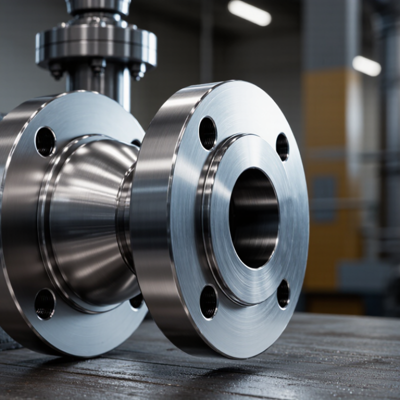
Top 10 Ways to Ensure Zero Leakage with Metal-Seated Balls
Understanding Leakage Risks in Metal-Seated Ball Valves
Metal-seated ball valves face leakage risks when sealing surfaces lose contact. Tiny scratches can create a visible pressure drop. High temperatures may also change clearances between the ball and seats. In field inspections, debris often causes more trouble than expected. A single metal chip can prevent complete closure.
Choose seat and ball materials for the fluid, pressure, and temperature. Check surface hardness and finish before assembly. Keep internal parts clean. Confirm that the ball aligns correctly with both seats. Incorrect alignment creates uneven loading and local wear. Apply the manufacturer’s specified torque carefully. Excessive force can damage sealing edges.
Pressure testing should match the valve’s actual service conditions. Test after installation, not only in the workshop. Thermal cycling deserves attention. A valve that passes at room temperature may leak after repeated heating and cooling. Inspect actuator travel, packing, and body connections too. Record test pressure, duration, temperature, and observed leakage. These details support reliable maintenance decisions.
Zero leakage sounds absolute. Real systems are less perfect. Some failures come from installation habits, not valve design. That is why inspection results should challenge assumptions. Recheck valves after vibration, abrasive service, or long idle periods. Small warning signs matter.
| No. | Leakage Risk | Preventive Method | Recommended Verification | Relevant Engineering Basis |
|---|---|---|---|---|
| 1 | Solid particles trapped between the ball and seats | Install effective upstream filtration where process conditions permit, flush the line before commissioning, and keep the valve fully open during pipeline cleaning when the valve design allows it. | Inspect the line for debris after flushing and perform a seat leakage test using the specified test medium and pressure. | Valve cleanliness requirements and the project commissioning procedure. |
| 2 | Incorrect ball-to-seat contact caused by poor alignment | Use accurately machined components, control body and stem tolerances, and follow the manufacturer’s assembly sequence without forcing the ball into position. | Check assembly records, stem alignment, operating torque, and repeatable shutoff from both required flow directions. | Approved manufacturing drawings, inspection plans, and valve assembly procedures. |
| 3 | Seat or ball damage from erosion and high-velocity flow | Select suitable seat materials and trim hardness for the service, avoid continuous operation near excessive velocity limits, and evaluate flashing or cavitation risk. | Review process velocity and pressure-drop calculations, then inspect the ball and seats for grooves, pitting, or loss of coating during maintenance. | Process design calculations, material compatibility data, and erosion-resistance criteria. |
| 4 | Thermal expansion causing excessive seating load | Evaluate differential thermal expansion between the ball, seats, and body; provide a suitable cavity-pressure-management design where required. | Confirm operating torque across the complete temperature range and check that cavity pressure remains within the design limit. | Design pressure-temperature rating, thermal expansion calculations, and applicable valve design requirements. |
| 5 | Wrong seat material for the fluid or temperature | Match metallic seat, ball, coating, and body materials to corrosion, erosion, temperature, pressure, and fluid contamination conditions. | Review material certificates, hardness results, coating inspection reports, and compatibility documentation before installation. | Material specifications, corrosion assessment, and process fluid compatibility review. |
| 6 | Insufficient or uneven actuator torque | Size the actuator for maximum breakaway, running, and seating torque, including friction, differential pressure, temperature, and an appropriate engineering margin. | Perform a functional test at the specified differential pressure and record open, close, and seating torque or actuator output. | Actuator sizing calculations, torque curves, and functional test procedures. |
| 7 | Stem seal leakage mistaken for seat leakage | Use a suitable stem sealing arrangement, install packing correctly, and provide accessible packing adjustment or a replaceable stem-seal design where appropriate. | Conduct a separate external-emission or stem-seal inspection while the valve is pressurized, in addition to the internal seat test. | External leakage requirements, packing specifications, and emissions-control procedures. |
| 8 | Improper installation or pipe strain | Align the connecting pipework, support the valve and actuator independently where necessary, use the correct gasket and bolt procedure, and prevent forced flange alignment. | Check flange alignment, bolt tightening records, support conditions, and valve operation before and after hydrostatic or pneumatic testing. | Piping installation specifications, flange assembly procedures, and applicable piping codes. |
| 9 | Inadequate or inconsistent pressure testing | Define the test medium, pressure, stabilization time, test direction, acceptance rate, and safety controls before testing. Test the body and seats separately when required. | Record calibrated gauge identification, test pressure, duration, temperature, test direction, and observed leakage against the approved acceptance criterion. | The project test specification and the applicable valve pressure-testing standard, such as ISO 5208 or API 598. |
| 10 | Wear, corrosion, or loss of coating during service | Establish a risk-based maintenance program that includes cycling checks, torque trending, cavity inspection where possible, and replacement of worn sealing components. | Trend shutoff performance over time and repeat the specified seat and external leakage tests after overhaul or when performance changes. | Inspection and maintenance plan, service history, and the valve’s original acceptance criteria. |
Leakage begins when the ball and seats lose full contact. Tiny scratches can create visible pressure loss. Debris is a common cause. One metal chip may prevent complete closure.
Match materials with the fluid, pressure, temperature, and operating cycles. Consider corrosion, abrasion, thermal expansion, and chemical exposure. A hard ball and equally hard seat may suffer surface damage. One material combination rarely suits every pipeline.
Heating can change the clearance between the ball and seats. A tight cold fit may loosen during operation. Repeated heating and cooling can reveal leakage missed at room temperature. Thermal cycling deserves testing.
Check ball roundness, seat concentricity, contact width, and surface finish. Both parts should share one centerline. Rough surfaces create leakage paths. Overly smooth surfaces may reduce lubricant retention or suffer contact damage.
Clean internal parts before assembly and final testing. Keep finished sealing surfaces protected from dust and chips. A single particle can scratch a seat. Cleanliness sounds basic, but it is often overlooked.
Correct alignment distributes contact pressure across both seats. Poor alignment creates uneven loading and local wear. Inspect contact patterns during testing. Perfect-looking parts may still leak after incorrect assembly.
Test under conditions close to actual service pressure and temperature. Test after installation, not only in the workshop. Record pressure, duration, temperature, and observed leakage. A room-temperature pass is not enough.
Yes. Excessive torque can damage sealing edges and increase wear. Verify actuator travel and use the specified torque carefully. Do not assume more force creates a better seal.
Recheck the valve after vibration, abrasive service, or long idle periods. Inspect packing and body connections as well. Compare field results with workshop records. Sometimes installation habits explain the failure. That possibility deserves honest review.
Achieving reliable zero leakage in metal-seated ball valves requires attention to every stage of design, production, installation, and service. The first step is understanding potential leakage risks, including thermal expansion, particle damage, seat wear, improper alignment, and insufficient contact pressure. Selecting compatible materials for the ball, seat, and sealing components helps prevent corrosion, galling, and premature deterioration under operating conditions. Precise machining, consistent tolerances, and suitable surface finishes are also essential for creating a uniform sealing interface.
To understand how to ensure a zero-leakage seal with metal-seated balls, installation and torque procedures must be carefully controlled. Excessive or insufficient torque can damage sealing surfaces or prevent proper closure. After installation, pressure and functional testing should confirm valve performance, while regular monitoring can identify wear, contamination, or changes in operating behavior. Planned maintenance, timely cleaning, and inspection of critical components help preserve sealing reliability and extend service life.
